
|
Since turbocharging my IS300 this summer, I've been plagued with P0420 & P0430 codes -- Catalyst System below Efficiency. I tried simulating the output with my Innovate Wideband MTX-L, but after many months and configurations, I've given up. So I built a simulator based on a 555 Timer IC. I will install the new simulator tonight and report back w/ the results. Hopefully CEL free! You can find the original schematics and instructions here. http://mkiv.com/techarticles/oxygen_sensor_simulator/index.html 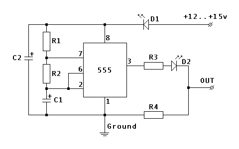 R1 100 K Ohm R2 1 M Ohm R3 100 K Ohm R4 10 K Ohm C1 4.7 uF Electrolytic C2 22 uF Electrolytic D1 1.7v@20mA LED D2 1.7v@20mA LED This is meant to fool the ECU into thinking the post-cat O2 sensors are working and the catalyst is within spec. IMPORTANT NOTE: If you build this, make sure you do not leave PIN 4 on the 555 timer open (floating). This will cause operation to stop and/or reset with even the slightest EMF or input voltage variation. Instead, connect PIN 4 to Input Power. I connected to PIN 8 and it works flawlessly. The only other improvement would be a smoothing capacitor on the output - just to make the signal more of a SINE wave as opposed to the square wave.
47 Comments
Jared
5/27/2015 10:34:39 am
Did the O2 simulator work on your IS300? Thanks
Jon @ Chippernut
5/28/2015 12:05:16 am
Yes - it worked fantastic. In this example I built two simulators on one board, but you only need one. You can drive both O2 signals by splitting the signal and inputting both to the ECU. Works great. Been CEL free since install.
Mustafa Ayvaz
3/25/2022 05:46:17 am
I couldn't find a 1.7v 20 amp led here. What else can I use instead?
Jared
6/1/2015 03:16:03 pm
Just built mine like you advised, it works great. One last question, did you weather proof it some how or did you just tuck it in the ecu box? Thanks!
Jon @ Chippernut
6/2/2015 12:11:35 am
I ended up putting mine in the same box as the shift light Arduino -- which is a small project box located under my dash. You could weatherproof it and put it under the hood though, or I like your idea of tucking it in the ECU box (if it'll fit). Just keep it away from excess heat and water/mud. Glad you got it to work!!
Kelly
10/27/2015 12:28:19 pm
I'm not very savvy when it comes to stuff like this, but I'm very interested. How would I go about figuring out what I'm looking at, or how to properly execute this? My CEL is currently on, and I am all for a cheap fix. Thanks.
Jon @ Chippernut
10/27/2015 12:52:22 pm
Hi Kelly,
Joel1212
7/23/2016 07:11:42 pm
Did u ever post details on my.is? O2 sims are going for big bucks and it would be great to build one myself but like the previous poster I need more info n parts list
Farmer john
5/26/2016 11:38:34 am
What do you do with prong 5? And are the led lights needed?
Jon @ Chippernut
5/26/2016 12:57:29 pm
I believe you just leave pin #5 disconnected. And yes, the LED's function as diodes and provide a small load to help it function correctly. Hope this helps
Zack
12/21/2016 10:06:25 am
Is this a plug and play type component or do i need to open up the ECU and do some cutting?
Jon @ Chippernut
12/21/2016 01:41:36 pm
Hi Zack,
Dave
12/4/2017 08:57:28 pm
Where can I get the equations for this?
Gary Charlton
2/14/2018 11:23:39 am
Would the input positive be switched or constant?
Jon @ Chippernut
2/15/2018 08:16:51 pm
It can be either - I have it wired up to constant in my car, it draws very little current, but it will drain the battery slowly over time. Switched input would probably be better. if you connect it to a power circuit that's powered when the key is in the "ON" position. Then it's only running when the vehicle is running.
DJ
4/8/2018 03:41:49 pm
Does the control voltage (pinout #5 need to be connected to anything?
Jon @ Chippernut
4/19/2018 07:46:06 pm
No - you can leave this open. Hope this helps. Sorry for the delayed response.
Randell T gribben
4/26/2019 03:53:07 pm
Question, on the positive side, how do you reduce the voltage from 12 volts to 1.5 volts that I see here, 12 volts directly to the first led, would get it instantly
James
8/17/2019 07:43:32 pm
So there is 12v across the supply rail(12v) and there is a 10k ohm resistor to groud plus the diode ((LED). There is 0.6v across a diode typically (this is the voltage required for forward conduction of a P-N) junction.
Randell T gribben
4/27/2019 06:07:11 pm
The input is from the evil to sendor/ 555. And output from 555 to ecu?
DJ
10/18/2019 12:49:52 pm
Hi Jon, after building the circuit, I have a 6.9v signal coming from the output, the only issue is it not flipping every 3.3sec like originally designed, any help would be appreciated!
John
6/23/2020 03:33:54 am
This looks great I want to try this as I'm getting the efficiency error. I tried putting a capacitor along with a resistor on the blue and white wires which is supposed to smooth out the output but for some reason for me it creates a higher voltage. Can you kindly tell me how this works? how is it taking the 15-12v input and converting it to 0.1-0.9V in the waveform that O2 sensor does? 6/24/2020 09:34:49 pm
Hi John! This circuit uses a 'voltage divider' R3 and R4 to bring the voltage to a max of 1v. Adding a capacitor across these lines changes the voltage output because the capacitor has a lower resistance than the resistor. Check out this link and put the values for R3 and R4. http://www.ohmslawcalculator.com/voltage-divider-calculator
John
6/27/2020 11:27:13 am
Thank you. So you suggest first just connect +12v from ignition to the in on the top right and connect ground from the car to the ground at the bottom of the diagram. Then connect the output only to the signal wire that usually goes from the o2 sensor to the ECU. So basically don't let the signal wire from o2 sensor go to ECU instead the output from this goes there. Ane the ground wire from the o2 sensor you suggest to cut it and leave it disconnected and see as the ECU should already be grounded?
John
6/27/2020 01:14:02 pm
Is the waveform supposed to look something like this: https://i.imgur.com/1ONNU4S.png
John
6/27/2020 02:28:34 pm
I've just quickly drawn up how i'm understanding to wire it up. Is it supposed to be something like this? https://i.imgur.com/Ey9oHbh.png my blue wire on the o2 sensor is the + signal wire I believe. 4/22/2021 01:16:42 pm
You mentioned possibly putting a capacitor between R4 and OUT to smooth the output. What value? Electrolytic? Negative tied to R4?
Jon @ Chippernut
5/10/2021 10:32:19 pm
I don't know why I mentioned this. Typically the narrowband O2 has a pretty sharp crossover between states. A smoother crossover might even trigger a CEL for a slow responding O2. But, if this is your goal, I would start w /a small ceramic and expriment, trial/error w/ an oscilliscope until you get the waveform characteristics you desire. Sorry I can't be of more assistance.
Mark
9/5/2021 05:54:00 am
Is the range adjustable so that the square wave signal can be between .4 to .6 volts? Or does this only ramp up from 0 volts?
Jon @ Chippernut
9/16/2021 07:54:29 pm
Hi Mark, The voltage output is not adjustable in this design, but I'm sure you could by adjusing some of the resistor values. It might take some trial/error. Sorry I can't be of more assistance.
JasonB
11/20/2021 11:43:07 pm
Hello, thank you for publishing this circuit, i have built 2 of these and both circuit the out LED, flashing every apron 5 seconds, but it is not as bright as the input LED, I am using 1/4 watt resistors, my 2 capacitor's are Electrolytic 22uf/25volt & 4.7uf/63volt, my local shop didn't have a small voltage cap in the 4.7uf range, any help would be appreciated. When I connect a volt meter to the out in will peak unto 2 volts for a millisecond then down to .7volts, and then zero.
Nasir
11/21/2021 11:30:03 pm
Ffter making simulator ,tested but my output voltage is between 4.5 to 7.5 volts, which is much higher ,i used ne555p timer Ic ,with all resisters with same values mentioned here ,4.7 25 volts & 22uf 35 volts capacitor.
JasonB
11/22/2021 03:20:57 pm
Hi Nasir, you want to check that R4 is the correct value, 1/24/2022 01:26:47 am
Great article! Thank you for sharing this informative post, and looking forward to the latest one.
Oscar Sanchez
2/3/2022 12:42:18 pm
I want to buy a o2 sensor simulator already made, can you tell me where can I find one?
Christopher martin
2/6/2022 12:54:07 pm
https://drive.google.com/file/d/1E8qUP6jteNdtHcwp6d6V5DkDob8w4s24/view?usp=sharing
Christopher martin
2/7/2022 01:37:33 pm
Without the capacitor accross the output i get "b1 s2 heating circuit malfunction" .
Kyle
9/13/2022 09:07:05 pm
If you want you can try to stack a 10k on top of the 100k(R3 resistor) to make it 110k so it MAY* lower the Voltage in the Divider part of the circuit
Christopher martin
9/14/2022 01:17:04 am
I eventually got a remap and got a rear o2 delete. Wanted a remap anyway as i had bigger turbo and no cats
Jason Florey
3/20/2022 11:13:07 am
Dude, which year model is your car? I have a 2006 gs300 with ecu issues and in our current times, I don't trust availability on re-worked electronics. I'm a tekkie with the spare parts for the build. My impacted systems are the transmission, EVAP, and headlights. Thanx
al
11/23/2022 10:35:36 am
just build it, it works...
MJ
2/6/2023 04:47:42 pm
My token solutions is flashing a red led and not working on my ‘02 IS 300. Does anyone here fix or can build me a new one? Am in Socal need to get it re-registered 2 weeks ago.
Sean
8/21/2023 06:24:56 am
Good morning! I have created the circuit as well I do have some questions.
Gary
11/4/2023 11:07:16 pm
So I am trying to put one of these together but the only issue I am running in to is I see you only have 2 wires coming off of it which I am assuming are the 12v input and the out to the ecm signal. How are you grounding it?
Sean
11/16/2023 05:30:37 pm
You need multimeter and o2 sensor does not use 12v unless you are pinning heated circuit (if it has that) Leave a Reply. |
AuthorJon @ Chippernut Archives
July 2024
Categories |
 RSS Feed