Chippernut Electronic Kits
  • Home
  • Blog
  • TECH
  • Products
  • Contact
  • FAQ

Moving

2/24/2015

0 Comments

 
Hi Everyone! I have good news and bad news. The good news is I'm moving -- due to a personal opportunity, I'm relocating from Milwaukee, WI to Chicago, IL. Unfortunately that means my posts over the next-few weeks may be limited. I'll do my best to respond to emails and monitor the forums though. (that's the bad news). I'm excited for this next chapter in my life though and I look forward to continue developing for Chippernut once things get settled. 
Picture
Diagram 1: Illustrating the great journey of 2015.
Picture
The results are in from the poll I posted on the home-page. This is very interesting data. If you can think of other polls/surveys I should do, please leave a comment in the box.  From these results, I'm going to put the 52mm gauge on hiatus and instead design some NeoPixel support structures. This is advantageous, because they will be more simple than the complex DIY gauge I was designing.  
0 Comments

OpenXc Tachometer

2/4/2015

0 Comments

 
Picture
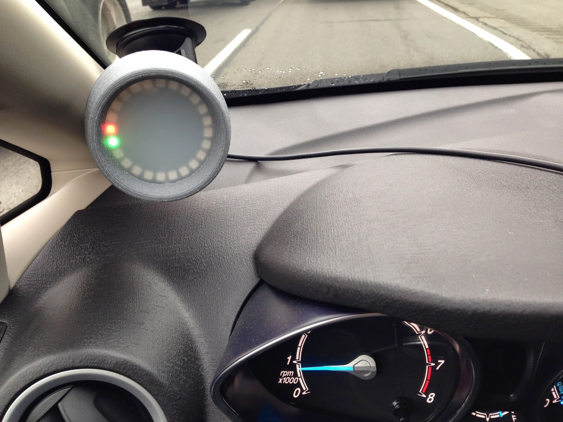
I was doing some research for the Chippernut Gauges and I came across Pete's Blog - and his OpenXC Tachometer for his Ford Fiesta. Very clean installation and unique application!  The nice thing about this is it doesn't involve tapping wires or the risk associated with messing with the ECU. Just plug in the OBD adapter and go-to-town!  Awesome!!! 
0 Comments

O2 Simulator

2/2/2015

43 Comments

 
Since turbocharging my IS300 this summer, I've been plagued with P0420 & P0430 codes -- Catalyst System below Efficiency. I tried simulating the output with my Innovate Wideband MTX-L, but after many months and configurations, I've given up. So I built a simulator based on a 555 Timer IC. I will install the new simulator tonight and report back w/ the results. Hopefully CEL free!

You can find the original schematics and instructions here. 
http://mkiv.com/techarticles/oxygen_sensor_simulator/index.html
Picture

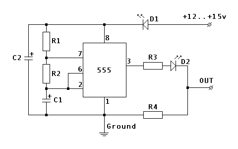
R1  100 K Ohm
R2  1 M Ohm
R3  100 K Ohm
R4  10 K Ohm
C1  4.7 uF Electrolytic
C2  22 uF Electrolytic
D1  1.7v@20mA LED
D2  1.7v@20mA LED

This is meant to fool the ECU into thinking the post-cat O2 sensors are working and the catalyst is within spec. 
IMPORTANT NOTE: If you build this, make sure you do not leave PIN 4 on the 555 timer open (floating).  This will cause operation to stop and/or reset with even the slightest EMF or input voltage variation.  Instead, connect PIN 4 to Input Power. I connected to PIN 8 and it works flawlessly. 


The only other improvement would be a smoothing capacitor on the output - just to make the signal more of a SINE wave as opposed to the square wave.
43 Comments

    Author

    Jon @ Chippernut 

    Archives

    April 2022
    March 2022
    April 2020
    May 2019
    August 2018
    June 2018
    May 2018
    April 2018
    March 2018
    December 2017
    September 2017
    August 2017
    June 2017
    December 2016
    September 2016
    July 2016
    June 2016
    April 2016
    March 2016
    February 2016
    December 2015
    November 2015
    October 2015
    September 2015
    August 2015
    July 2015
    June 2015
    May 2015
    April 2015
    March 2015
    February 2015
    January 2015
    December 2014
    November 2014
    October 2014
    August 2014
    July 2014

    Categories

    All

    RSS Feed

    This website uses marketing and tracking technologies. Opting out of this will opt you out of all cookies, except for those needed to run the website. Note that some products may not work as well without tracking cookies.

    Opt Out of Cookies
  (c) 2019 Chippernut, LLC.
Privacy 
  • Home
  • Blog
  • TECH
  • Products
  • Contact
  • FAQ